Die Cut Flexible Materials: Part Tolerances and Hole Placement

 Engineers who design metal parts are familiar with manufacturing processes such as machining, spinning, and stamping. Similarly, engineers who specialize in rigid plastic components learn about design guidelines for plastic machining, injection molding, and thermoforming. Die cutting is a versatile and cost-effective parts production technique, but the design guidelines that apply to metal and rigid plastic parts aren’t identical to the ones for die cut flexible materials.
Part tolerances are important to consider, especially when project deadlines are tight and a design issue could delay production or assembly downstream. Ultimately, the best time to address potential challenges is before releasing your drawing, blueprint, or CAD file for flat bed or rotary die cutting. By working with an experienced die cutter like JBC Technologies, engineers can optimize part designs for flexible gasket materials like foams and rubber.
Part Tolerances for Die Cut Parts
Part tolerances are allowable variations in the physical dimensions of manufactured components. They’re expressed as plus or minus values, or as a range of measurements. If a part is out of tolerance, problems with larger assemblies may occur. For example, if a rubber door seal on a machine is out of tolerance, the door may be difficult to shut or fail to provide proper environmental sealing and acoustic insulation. Rubber has different properties than metal, too, and responds differently to changes in temperature.
There’s also a great deal of variability in how die cut flexible materials respond to temperature changes. This phenomena, which is expressed as the coefficient of thermal expansion, measures the fractional change-in-size per degree of change-in-temperature. This sensitivity to temperature change can affect the size of the part and possibly lead to failure. For more information, download our case study called “Engineering-Minded Die Cutter Finds Solution for Automotive Company in Panic Mode.”
The kind of tooling that’s used in die cutting can also affect part tolerances for rubber gaskets. Design engineers may need to account for the type of die that’s used, especially with flexible materials that are subject to shrinkage or distortion. As a rule, don’t specify the same tolerances as you would for metal or rigid plastic parts. Instead, refer to published tolerance tables from the Rubber Manufacturers Association (RMA). The team at JBC Technologies can also answer your questions about part tolerances.
Hole Placement for Die Cut Products
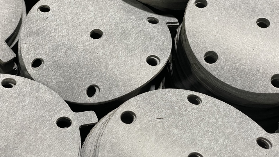
With flexible materials, bolt holes that are spaced too close together can cause problems such as ripping, splitting, or tearing. As we learned in last week’s blog entry, however, engineers can avoid these problems by designing gaskets that minimize manufacturing risks and still support form, fit, and function. If your gasket designs contain a line of bolt holes that are spaced closely together, consider replacing these multiple openings with a single oblong feature that can accommodate all of the bolts. Remember: the gasket may not have to be identical to the sealing surface to perform its job.
There are other factors to consider as well. Sharp, square corners can create weak points in flexible materials. If your gasket design specifies square or rectangular part features, tool deflection and localized material deformation may occur. Assembly hole locations are dictated by part or product function, and moving the location of mounting holes to accommodate die cutting isn’t an option. Still, by adjusting your part designs in other ways, however, you can achieve optimal die cutting.
Are You a Die Cutting Deity?
Do you have questions about die cutting for flexible materials? You don’t have to have all the answers. You just need to know where to find them. Whether your application requires flatbed die cutting or rotary die cutting, JBC Technologies can help you to optimize your part designs. For more information, please contact us.